|
■2013年04月22日(月)08:55
Another try using LTC2440 24-bit ADC
|
 | http://dangerousprototypes.com/forum/viewtopic.php?f=2&t=4247&p=42053#p42051
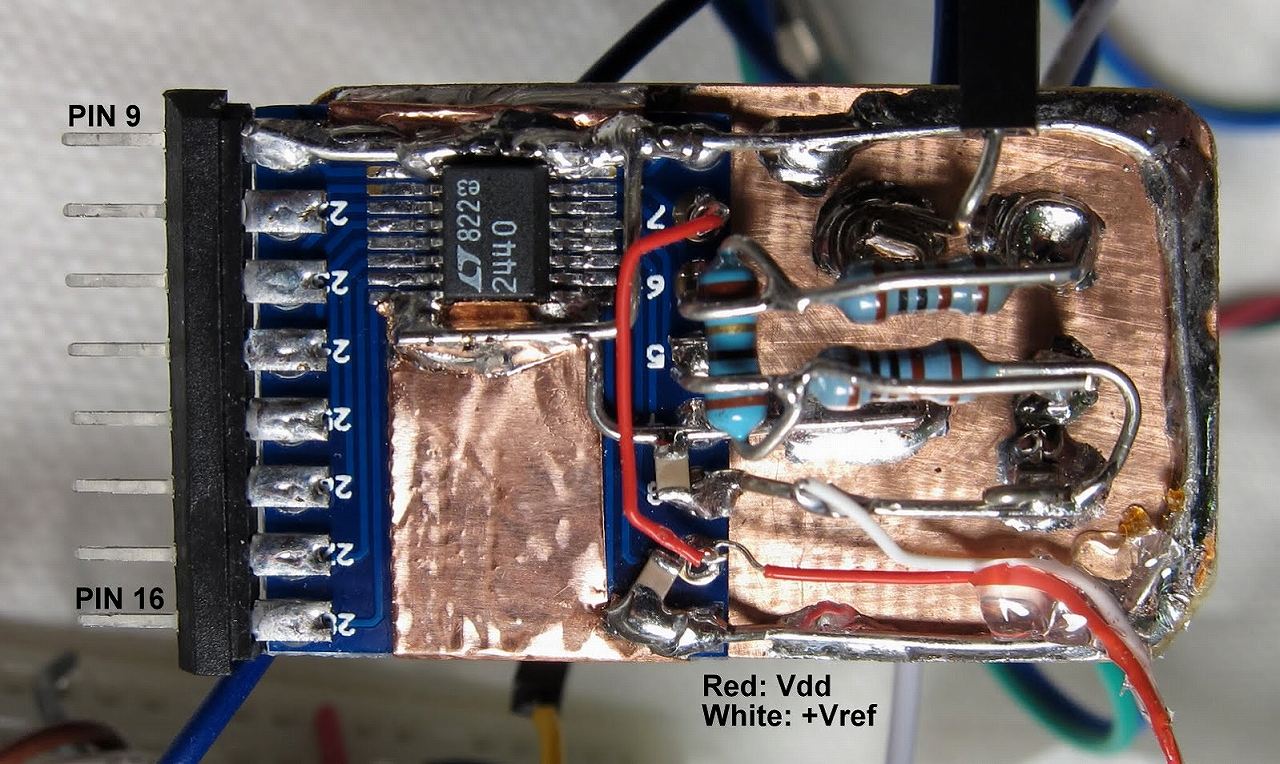
Success! I finally got the datasheet-specified noise performance from the LTC2440 ADC. I made a new circuit with more attention to very low-impedance grounds, and I built it SIP-style with the digital side having pins, and the analog portion on its own ground plane without directly contacting the breadboard. My signal is as before, two 1k resistors forming a divider from +Vref to -Vref (GND) and a 10 ohm resistor between +IN and -IN to give me a signal of about (5V/2.01k)*10 ohms = 25 mV with a common-mode voltage of 2.5 V. This circuit shows 198 nV (rms) noise, right at the spec level (200 nV) for the 6.9 Hz output rate. You can see after turning on the circuit, my 24.948 mV signal drifts down by less than one microvolt (!) and then levels off, over the course of 45 minutes. That is < 40 ppm stability.
What would I expect the drift to be? I assume the dominant error is thermal drift of the 1k resistors. Taking a wild guess, say a 1/4 watt resistor is 400 C/W, and at 2.5 mA current each 1k resistor dissipates I^2*R = 6.25 mW, so dT = 2.5 C temperature rise. I think these parts are spec'd to be 100 ppm/C, so looks like they're at least 4x better than their spec limit- not too bad.
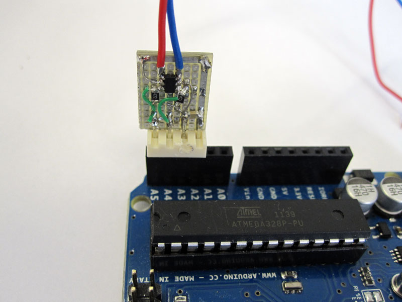
The earlier prototype (first few posts in this thread) used the adaptor board DIP-style with the analog connections on the solderless breadboard, and it never got below 250 nV (rms) with semi-periodic sudden signal jumps of about 1 uV. I believe that was related to the mechanical pressure contacts making the wire connections inside the breadboard; they are not suited to clean signals at the microvolt level.
/*
Interface between Arduino DM board and Linear Tech LTC2440 24-bit ADC
Oct. 24 2012 John Beale
LTC2440 <----------> Arduino
10: /EXT : ground (use external serial clock)
11: /CS <- to digital pin 10 (SS pin)
12: MISO -> to digital pin 12 (MISO pin)
13: SCLK <- to digital pin 13 (SCK pin)
15: BUSY -> to digital pin 9 (low when result ready)
1,8,9,16: GND : all grounds must be connected
2: Vcc : +5V supply
3: REF+ : +5V reference
4: REF- : GND
5: IN+ : Input+
6: IN- : Input-
7: SDI : +5V (select 6.9 Hz output rate, or GND for 880 Hz rate)
14: Fo : GND (select internal 9 MHz oscillator)
*/
#include // include the SPI library
#include // from http://code.google.com/p/digitalwritefast/downloads/list
// I had to update the WriteFast library for Arduino 1.0.1: replace "#include wiring.h" and "#include WProgram.h"
// with "#include " in libraries/digitalwritefast/digitalWriteFast.h
#define VREF (5.0) // ADC voltage reference
#define PWAIT (198) // milliseconds delay between readings
#define SLAVESELECT 10 // digital pin 10 for CS/
#define BUSYPIN 9 // digital pin 9 for BUSY or READY/
const int nsamples = 50; // how many ADC readings to average together
// SPI_CLOCK_DIV16 gives me a 1.0 MHz SPI clock, with 16 MHz crystal on Arduino
void setup() {
Serial.begin(115200); // set up serial comm to PC at this baud rate
pinMode (SLAVESELECT, OUTPUT);
pinMode (BUSYPIN, INPUT);
digitalWriteFast(SLAVESELECT,LOW); // take the SS pin low to select the chip
delayMicroseconds(1);
digitalWriteFast(SLAVESELECT,HIGH); // take the SS pin high to start new ADC conversion
SPI.begin(); // initialize SPI, covering MOSI,MISO,SCK signals
SPI.setBitOrder(MSBFIRST); // data is clocked in MSB first
SPI.setDataMode(SPI_MODE0); // SCLK idle low (CPOL=0), MOSI read on rising edge (CPHI=0)
SPI.setClockDivider(SPI_CLOCK_DIV16); // set SPI clock at 1 MHz. Arduino xtal = 16 MHz, LTC2440 max = 20 MHz
Serial.println("# LTC2440 v1.1 Oct.25 2012 jpb");
Serial.println("min,uVolts,pkpk,stdev");
for (int i=0;i<2;i++) { // throw away the first few readings, which seem to be way off
SpiRead();
}
} // end setup()
// =============================================================================
// Main Loop:
// acquire 'nsamples' readings, convert to units of volts, and send out on serial port
void loop() {
int i;
long secs;
float mins;
long in; // incoming serial 32-bit word
float uVolts; // average reading in microvolts
float datSum; // accumulated sum of input values
float sMax;
float sMin;
long n; // count of how many readings so far
float x,mean,delta,sumsq,m2,variance,stdev,pp; // to calculate standard deviation
sMax = -VREF; // set max to minimum possible reading
sMin = VREF; // set min to max possible reading
sumsq = 0; // initialize running squared sum of differences
n = 0; // have not made any ADC readings yet
datSum = 0; // accumulated sum of readings starts at zero
mean = 0; // start off with running mean at zero
m2 = 0;
for (i=0; i x = SpiRead();
datSum += x;
if (x > sMax) sMax = x;
if (x < sMin) sMin = x;
// from http://en.wikipedia.org/wiki/Algorithms_for_calculating_variance
n++;
delta = x - mean;
mean += delta/n;
m2 += (delta * (x - mean));
} // end for (i..)
variance = m2/(n-1); // (n-1):Sample Variance (n): Population Variance
stdev = 1E6*sqrt(variance); // Calculate standard deviation in microvolts
pp = 1E6 * (sMax - sMin); // peak-to-peak difference of readings, in uV
uVolts = datSum * (1E6) / n;
mins = (float) millis() / 60000; // elapsed time in minutes
Serial.print(mins,3);
Serial.print(", ");
Serial.print(uVolts,3);
Serial.print(", ");
Serial.print(pp,3);
Serial.print(", ");
Serial.print(stdev,3);
Serial.println();
} // end main loop
// =================================================================
// SpiRead() -- read 4 bytes from LTC2440 chip via SPI, return Volts
// =================================================================
float SpiRead(void) {
long result = 0;
byte sig = 0; // sign bit
byte b;
float v;
while (digitalReadFast(BUSYPIN)==HIGH) {} // wait until ADC result is ready
digitalWriteFast(SLAVESELECT,LOW); // take the SS pin low to select the chip
delayMicroseconds(1); // probably not needed, only need 25 nsec delay
b = SPI.transfer(0xff); // B3
if ((b & 0x20) ==0) sig=1; // is input negative ?
b &=0x1f; // discard bits 25..31
result = b;
result <<= 8;
b = SPI.transfer(0xff); // B2
result |= b;
result = result<<8;
b = SPI.transfer(0xff); // B1
result |= b;
result = result<<8;
b = SPI.transfer(0xff); // B0
result |= b;
digitalWriteFast(SLAVESELECT,HIGH); // take the SS pin high to bring MISO to hi-Z and start new conversion
if (sig) result |= 0xf0000000; // if input is negative, insert sign bit (0xf0.. or 0xe0... ?)
v = result;
v = v / 16.0; // scale result down , last 4 bits are "sub-LSBs"
v = v * VREF / (2 * 16777216); // +Vfullscale = +Vref/2, max scale (2^24 = 16777216)
return(v);
} | | |

