日記

[HOME] [画像] [] [] [検索]
過去ログ 2004年07月 08月 10月 
2005年01月 08月 10月 11月 12月 
2006年01月 02月 03月 04月 05月 06月 07月 08月 09月 10月 12月 
2007年01月 02月 03月 04月 05月 06月 07月 08月 09月 10月 11月 12月 
2008年01月 02月 03月 04月 05月 06月 07月 08月 09月 10月 11月 12月 
2009年01月 02月 03月 04月 05月 06月 07月 08月 09月 10月 11月 12月 
2010年01月 02月 03月 04月 05月 06月 07月 08月 09月 10月 11月 12月 
2011年01月 02月 03月 04月 05月 06月 07月 08月 09月 10月 11月 12月 
2012年01月 02月 03月 04月 05月 06月 07月 08月 09月 10月 11月 12月 
2013年01月 02月 03月 04月 05月 06月 07月 08月 09月 10月 11月 12月 
2014年01月 02月 03月 04月 05月 06月 07月 08月 09月 10月 11月 12月 
2015年01月 02月 03月 04月 05月 06月 07月 09月 10月 11月 12月 
2016年01月 02月 03月 04月 05月 10月 
2017年01月 

REF 2013, 04, 29, (月)
ADR5044BRTZ-R2
タイプ Precision
チャネル数 1
基準電圧 4.096V
出力電圧精度 ±0.1%
パッケージ SOT-23
1〜@¥135
10〜@¥122
25〜@¥109
100〜@¥98.4
https://www.chip1stop.com/dispDetail.do?partId=AD01-0028280


タイプ Precision
チャネル数 1
基準電圧 4.096V
出力電圧精度 0.05%
1〜@¥384
25〜@¥309
100〜@¥185
https://www.chip1stop.com/dispDetail.do?&partId=TI01-0146525


ADR444BRZ / XFET 電圧リファレンス
ADR444BRZ 8 ld SOIC チューブ Yes
\557 40ケ
http://www.furutaka-netsel.co.jp/maker/analogdevices/ADR444BRZ.html


MAX6341CSA+
タイプ 基準電圧: シリーズ、埋め込みツエナー
チャネル数 1
基準電圧 4.096V
出力電圧精度 ±0.02%
1〜@¥1,510
25〜@¥1,290


2013, 04, 28, (日)
ADS1232REF 5,060
http://www.digikey.jp/product-detail/ja/ADS1232REF/296-20803-ND/1216408


ADS1232IPW
http://www.chip1stop.com/dispDetail.do?partId=TI01-0141631


http://www.sengoku.co.jp/mod/sgk_cart/detail.php?code=6ATA-CKDE
KDK HC−49/U 4.9152MHz
水晶振動子 4.9152MHz
負荷容量:16pF 発振モード:Fund 周波数偏差:±30ppm 動作温度:−20℃〜+70℃
寸法:11.05×4.65×13.46mm ピッチ:4.88mm
【数量1個〜】 単価 \158


ADS1246
http://www.tij.co.jp/product/jp/ads1246
http://www.chip1stop.com/search.do

電圧&電流計アダプタ 2013, 04, 27, (土)
http://www8.plala.or.jp/InHisTime/page111.html#PIC-194
<仕様>
      ・電圧の測定表示は、分解能=100mVとします。<50点バー表示機能搭載>
      ・電流の測定表示は、分解能=100mAとします。<50点バー表示機能搭載>
      ・電圧の測定範囲を設定可能とします。
        :最小5V=5V×1倍
        :最大5000V=5V×1000倍 → 表示上は99.9Vが最大となります。
      ・電流検出抵抗の値を設定可能とします。
        :0.01Ω〜10Ω
      ・電流の測定範囲を設定可能とします。
        :電流検出抵抗の値と電圧増福率の値の組み合わせで範囲を決定します。
        :最小500μA=5V÷(10Ω×1000倍) → 表示上は100mAが最小となります。
        :最大500A=5V÷(0.01Ω×1倍) → 表示上は99.9Aが最大となります。


 ■簡易電圧計(高分解能22ビット)

http://www8.plala.or.jp/InHisTime/page009.html#PIC-177

<仕様>
      ◎MCP3551使用時
        ・分解能=0.9765625μV...4096mV÷22ビット(4194304)
        ・変換速度=約100msec
        ・参照電圧=4096mV
        ・入力=1チャネル(CH1)
      ◎PIC内蔵ADC使用時
        ・分解能=4mV...4096mV÷10ビット(1024)
        ・変換速度=約0.1msec
        ・参照電圧=4096mV
        ・入力=1チャネル(CH2)

*********************************
PIC マイコンの C 言語開発環境である MikroElektronika 社の mikroC PRO for PIC のインストー. ル方法と使い方 ... フォント名は、MS明朝などの日本語フォント、文字セットは日本語に設定
http://www.google.co.jp/url?sa=t&rct=j&q=&esrc=s&source=web&cd=1&cad=rja&ved=0CDIQFjAA&url=http%3A%2F%2Fecobioinfo.com%2Fusr%2Fdocuments%2FmikroC-manual.pdf&ei=YKJ-UYj7I8eHkAXO4ICIDw&usg=AFQjCNEL9z1SBbHvarEMCqsZyV78Uh0I3Q&sig2=kDlkywXXnXcgyLd00cQMLw&bvm=bv.45645796,d.dGI


周波数カウンタ 2013, 04, 27, (土)
周波数カウンタV9(PIC18シリーズ最小)
http://www8.plala.or.jp/InHisTime/page133.html#PIC-110

<仕様>
     ・ゲートタイム切り替え(1秒/0.1秒)
     ・-455kHz切り替え(有/無)
     ・表示切替(Hz/kHz)
     ・測定範囲(10Hz〜60MHz)

■2013年04月26日(金)01:13  SCD03HTR SCD10HTR
WS000039.JPG 1221×906 169K
http://suzushoweb.com/osusume.php

■ タイホープロダクト
■ 定格電流:±3A 電源電圧:±5V
■ RoHS対応 低ノイズ品

■ タイホープロダクト
■ 定格電流:±10A 電源電圧:±5V
■ RoHS対応 低ノイズ品

資料PDF(参考資料)
1個入 260円(税込)


資料PDF(参考資料)http://suzushoweb.com/pdf_file/4e13f1618836e.pdf
1個入 210円(税込)


■2013年04月26日(金)01:06  HTFS800-P/SP3
WS000031.JPG 647×868 119K
■ ナナ・レム
■ 電流センサー
■ Vref:2.5V IPN:800A

資料PDF(参考資料)http://suzushoweb.com/pdf_file/4d11c24640120.pdf
1個入 1,500円(税込)
http://suzushoweb.com/osusume.php

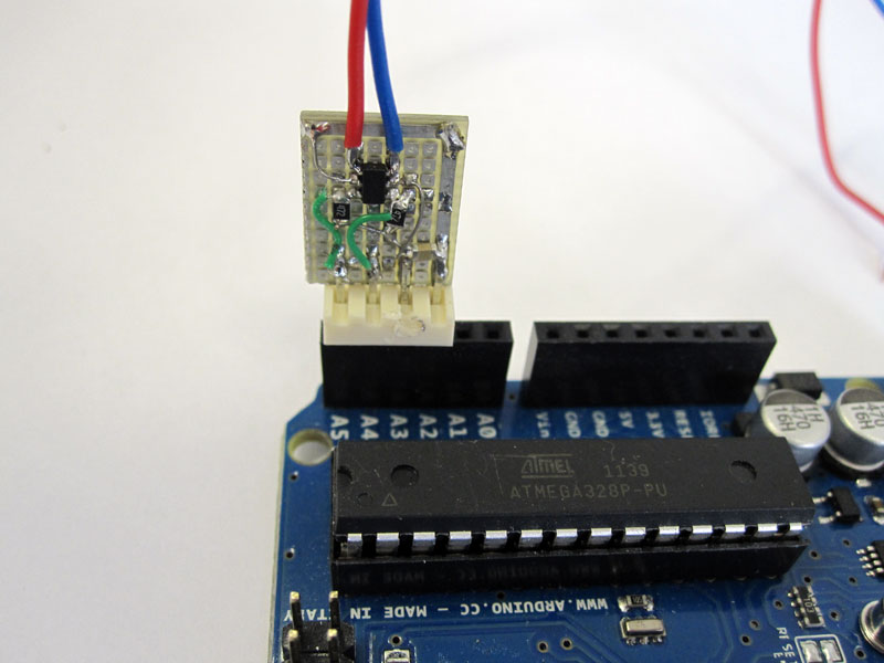
■2013年04月25日(木)01:38  MCP3421 18-Bit
IMG_3067web.jpg 800×600 59K
http://interface.khm.de/index.php/lab-log/connect-a-mcp3421-18-bit-analog-to-digital-converter-to-an-arduino-board/

MCP3421 18-Bit
http://interface.khm.de/index.php/lab-log/connect-a-mcp3421-18-bit-analog-to-digital-converter-to-an-arduino-board/


/* MCP3421 18-Bit Analog-to-Digital Converter with I2C Interface and On-Board Reference
* Lab3 3/2012 Nawrath
* Kunsthochschule fuer Medien Koeln
* Academy of Media Arts Cologne
* http://interface.khm.de

This program is free software: you can redistribute it and/or modify
it under the terms of the GNU General Public License as published by
the Free Software Foundation, either version 3 of the License, or
(at your option) any later version.

This program is distributed in the hope that it will be useful,
but WITHOUT ANY WARRANTY; without even the implied warranty of
MERCHANTABILITY or FITNESS FOR A PARTICULAR PURPOSE. See the
GNU General Public License for more details.

You should have received a copy of the GNU General Public License
along with this program. If not, see <http://www.gnu.org/licenses/>.

sr= Sample Rate Selection
sr=0 ; 00 = 240 SPS (12 bits),
sr=1 ; 01 = 60 SPS (14 bits),
sr=2 ; 10 = 15 SPS (16 bits),
sr=3 ; 11 = 3.75 SPS (18 bits)

pga= PGA Gain Selector
0 = 1 V/V,
1 = 2 V/V,
2 = 4 V/V,
3 = 8 V/V
*/


#include "MCP3421.h"
#include
#include


MCP3421::MCP3421() {
}

int MCP3421::init(int address, byte sr, byte pga) {

_adr = address; // set device address to 0x68 for MCP3421
_sr=sr & 3; // Sample Rate
_pga=pga & 3; // PGA ampification Factor

Wire.beginTransmission(_adr);

_confWrite=0;
_confWrite=_confWrite | ( _sr << 2 );
_confWrite=_confWrite | _pga;
bitWrite (_confWrite,7,1); // RDY
bitWrite (_confWrite,4,1); // O/C 1

Wire.write(_confWrite); // config register %1000 1000
// /RDY = 1, One Conversion, 15 samples per, PGA = X1
Serial.println(_confWrite,BIN);
Wire.endTransmission();


}
//**********************************************
long MCP3421::getLong() {

if (_sr < 3) {
Wire.requestFrom(_adr, 3);
_b2 = Wire.read();
_b3 = Wire.read();
_confRead = Wire.read();
Wire.endTransmission();
_l1= 256* _b2 +_b3;
} else {
Wire.requestFrom(_adr, 4);
_b2 = Wire.read();
_b3 = Wire.read();
_b4 = Wire.read();
_confRead = Wire.read();
Wire.endTransmission();
// _l1=_b4;

_l1= (long)_b3*256;
_l1=_l1+_b4;
_l1=_l1+0x10000 * _b2;
if ( _b2 > 0x10 ) _l1=_l1 + 0xFF000000;
}

return( _l1);
}

//**********************************************
double MCP3421::getDouble() {
getLong();
_db1= _l1 * 1e-3 / (1 << _sr*2 ) ; // = 1mv * ADC * / sample rate factor
_db1= _db1 / (1 <<_pga); // divide by pga amplificati
return( _db1);
}

//**********************************************
int MCP3421::ready() {
getLong();
return(!bitRead(_confRead,7));
}


■2013年04月25日(木)00:13  MCP3550 22-bit ADC test circuit
IMG_4961.JPG 1152×720 222K
https://picasaweb.google.com/109928236040342205185/Electronics?noredirect=1#5709914452360550594


電子工作etc
簡易電圧計(高分解能22ビット)PIC16F88
http://www8.plala.or.jp/InHisTime/page009.html

//**********************************************************************
/*
  <簡易電圧計(高分解能22ビット)>
*/
//**********************************************************************
//■マクロ定義
#define BYTE unsigned short
#define WORD unsigned int
#define DWORD unsigned long
//LCD
sbit LCD_RS at RB6_bit;
sbit LCD_EN at RB7_bit;
sbit LCD_D7 at RA1_bit;
sbit LCD_D6 at RA0_bit;
sbit LCD_D5 at RA7_bit;
sbit LCD_D4 at RA6_bit;
sbit LCD_RS_Direction at TRISB6_bit;
sbit LCD_EN_Direction at TRISB7_bit;
sbit LCD_D7_Direction at TRISA1_bit;
sbit LCD_D6_Direction at TRISA0_bit;
sbit LCD_D5_Direction at TRISA7_bit;
sbit LCD_D4_Direction at TRISA6_bit;
//
#define INPUT_MODE 1
#define OUTPUT_MODE 0
//**********************************************************************
//■関数宣言
extern void main();
extern long mcp3551_read();
extern void mcp3551_init();
//**********************************************************************
//■メイン関数
void main()
{
double v1;
WORD v2;
short cnt;
char buf1[16], buf2[16];
char *space = " ";
//
OSCCON = 0b01110000;
ANSEL = 0b00000100;
TRISA = 0b11111111;
TRISB = 0b00000100;
//
mcp3551_init();
ADCON1.VCFG1 = 1;
ADCON1.VCFG0 = 0;
ADC_Init();
//
Lcd_Init();
Lcd_Cmd(_LCD_CURSOR_OFF);
Lcd_Cmd(_LCD_CLEAR);
Lcd_Out(1, 1, "Voltmeter(22bit)");
Delay_ms(1000);
Lcd_Cmd(_LCD_CLEAR);
//
while (1) {
//測定
v1 = mcp3551_read();
v2 = ADC_Get_Sample(2);
//補正
v1 = v1 * 0.9765625; // 分解能=0.9765625uV = 4096000uV ÷ 4194304
v2 = v2 * 4; // 分解能=4mV = 4096mV ÷ 1024
//表示
FloatToStr(v1, buf1);
WordToStr(v2, buf2);
Lcd_Out(1, 1, "uV:");
Lcd_Out(2, 1, "mV:");
Lcd_Out(1, 4, space);
Lcd_Out(2, 4, space);
Lcd_Out(1, 4, buf1);
Lcd_Out(2, 4, &buf2[1]);
//
Delay_ms(500);
}
}
//**********************************************************************
//MCP3551
sbit CS at RB1_bit;
sbit SDO at RB2_bit;
sbit SCK at RB3_bit;
sbit CS_Direction at TRISB1_bit;
sbit SDO_Direction at TRISB2_bit;
sbit SCK_Direction at TRISB3_bit;
//
void mcp3551_init()
{
CS_Direction = OUTPUT_MODE;
SDO_Direction = INPUT_MODE;
SCK_Direction = OUTPUT_MODE;
//
CS = 1;
SCK = 1;
}
//**********************************************************************
long mcp3551_read()
{
long dat;
short cnt;
//
dat = 0;
CS = 0;
while (SDO == 1)
;
for (cnt = 0; cnt < 24; cnt++) {
SCK = 0;
SCK = 1;
if (SDO == 1) {
dat |= 0x01;
}
dat <<= 1;
}
CS = 1;
return (dat & 0b001111111111111111111111);
}
//**********************************************************************


24bit 2013, 04, 24, (水)
http://www.chip1stop.com/dispDetail.do?partId=TI01-0141888


■2013年04月22日(月)14:53  Connect a LTC2400 High Precision 24 Bit Analog to Digital Converter
WS000019.JPG 412×1039 67K
Connect a LTC2400 High Precision 24 Bit Analog to Digital Converter
http://interface.khm.de/index.php/lab/experiments/connect-a-ltc2400-high-precision-24-bit-analog-to-digital-converter/

/* LTC2400 24 Bit ADC Test
* Connect an LTC2400 24 Bit ADC to the Arduino Board in SPI Mode
*
*
*
* KHM 2009 / Martin Nawrath
* Kunsthochschule fuer Medien Koeln
* Academy of Media Arts Cologne

*/
#include

#ifndef cbi
#define cbi(sfr, bit) (_SFR_BYTE(sfr) &= ~_BV(bit))
#endif
#ifndef sbi
#define sbi(sfr, bit) (_SFR_BYTE(sfr) |= _BV(bit))
#endif

#define LTC_CS 2 // LTC2400 Chip Select Pin on Portb 2
#define LTC_MISO 4 // LTC2400 SDO Select Pin on Portb 4
#define LTC_SCK 5 // LTC2400 SCK Select Pin on Portb 5

void setup() {

cbi(PORTB,LTC_SCK); // LTC2400 SCK low
sbi (DDRB,LTC_CS); // LTC2400 CS HIGH

cbi (DDRB,LTC_MISO);
sbi (DDRB,LTC_SCK);

Serial.begin(57600);
// init SPI Hardware
sbi(SPCR,MSTR) ; // SPI master mode
sbi(SPCR,SPR0) ; // SPI speed
sbi(SPCR,SPR1); // SPI speed
sbi(SPCR,SPE); //SPI enable

Serial.println("LTC2400 ADC Test");

}
float volt;
float v_ref=3.0; // Reference Voltage, 5.0 Volt for LT1021 or 3.0 for LP2950-3

long int ltw = 0; // ADC Data ling int
int cnt; // counter
byte b0; //
byte sig; // sign bit flag
char st1[20]; // float voltage text

/********************************************************************/
void loop() {

cbi(PORTB,LTC_CS); // LTC2400 CS Low
delayMicroseconds(1);
if (!(PINB & (1 << PB4))) { // ADC Converter ready ?
// cli();
ltw=0;
sig=0;

b0 = SPI_read(); // read 4 bytes adc raw data with SPI
if ((b0 & 0x20) ==0) sig=1; // is input negative ?
b0 &=0x1F; // discard bit 25..31
ltw |= b0;
ltw <<= 8;
b0 = SPI_read();
ltw |= b0;
ltw <<= 8;
b0 = SPI_read();
ltw |= b0;
ltw <<= 8;
b0 = SPI_read();
ltw |= b0;

delayMicroseconds(1);

sbi(PORTB,LTC_CS); // LTC2400 CS Low
delay(200);

if (sig) ltw |= 0xf0000000; // if input negative insert sign bit
ltw=ltw/16; // scale result down , last 4 bits have no information
volt = ltw * v_ref / 16777216; // max scale

Serial.print(cnt++);
Serial.print("; ");
printFloat(volt,6); // print voltage as floating number
Serial.println(" ");

}
sbi(PORTB,LTC_CS); // LTC2400 CS hi
delay(20);

}
/********************************************************************/
byte SPI_read()
{
SPDR = 0;
while (!(SPSR & (1 << SPIF))) ; /* Wait for SPI shift out done */
return SPDR;
}
/********************************************************************/
// printFloat from tim / Arduino: Playground
// printFloat prints out the float 'value' rounded to 'places' places
//after the decimal point
void printFloat(float value, int places) {
// this is used to cast digits
int digit;
float tens = 0.1;
int tenscount = 0;
int i;
float tempfloat = value;

// if value is negative, set tempfloat to the abs value

// make sure we round properly. this could use pow from
//, but doesn't seem worth the import
// if this rounding step isn't here, the value 54.321 prints as

// calculate rounding term d: 0.5/pow(10,places)
float d = 0.5;
if (value < 0)
d *= -1.0;
// divide by ten for each decimal place
for (i = 0; i < places; i++)
d/= 10.0;
// this small addition, combined with truncation will round our

tempfloat += d;

if (value < 0)
tempfloat *= -1.0;
while ((tens * 10.0) <= tempfloat) {
tens *= 10.0;
tenscount += 1;
}

// write out the negative if needed
if (value < 0)
Serial.print('-');

if (tenscount == 0)
Serial.print(0, DEC);

for (i=0; i< tenscount; i++) {
digit = (int) (tempfloat/tens);
Serial.print(digit, DEC);
tempfloat = tempfloat - ((float)digit * tens);
tens /= 10.0;
}

// if no places after decimal, stop now and return
if (places <= 0)
return;

// otherwise, write the point and continue on
Serial.print(',');

for (i = 0; i < places; i++) {
tempfloat *= 10.0;
digit = (int) tempfloat;
Serial.print(digit,DEC);
// once written, subtract off that digit
tempfloat = tempfloat - (float) digit;
}
}

http://interface.khm.de/wp-content/uploads/2009/01/digitalconverter.zip

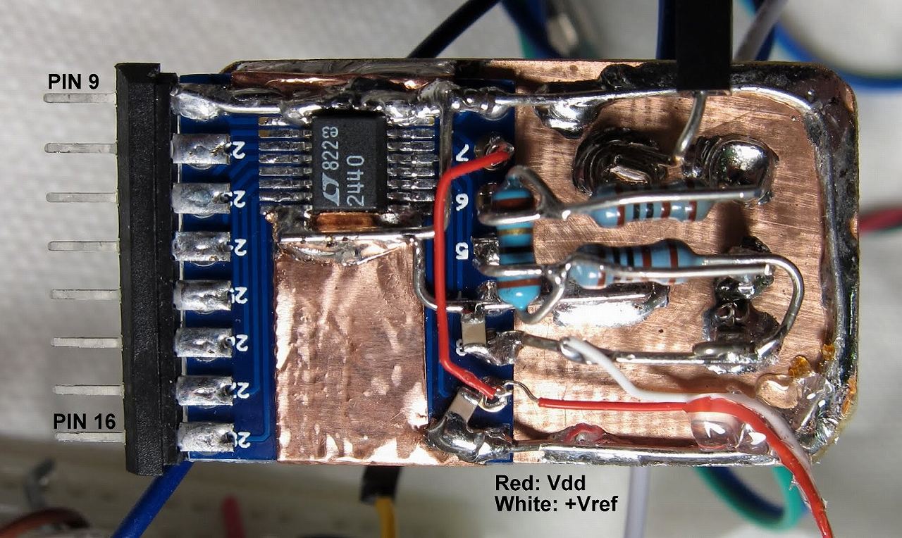
■2013年04月22日(月)08:55  Another try using LTC2440 24-bit ADC
s-IMG_2607.jpg 1280×764 197K
http://dangerousprototypes.com/forum/viewtopic.php?f=2&t=4247&p=42053#p42051
Success! I finally got the datasheet-specified noise performance from the LTC2440 ADC. I made a new circuit with more attention to very low-impedance grounds, and I built it SIP-style with the digital side having pins, and the analog portion on its own ground plane without directly contacting the breadboard. My signal is as before, two 1k resistors forming a divider from +Vref to -Vref (GND) and a 10 ohm resistor between +IN and -IN to give me a signal of about (5V/2.01k)*10 ohms = 25 mV with a common-mode voltage of 2.5 V. This circuit shows 198 nV (rms) noise, right at the spec level (200 nV) for the 6.9 Hz output rate. You can see after turning on the circuit, my 24.948 mV signal drifts down by less than one microvolt (!) and then levels off, over the course of 45 minutes. That is < 40 ppm stability.

What would I expect the drift to be? I assume the dominant error is thermal drift of the 1k resistors. Taking a wild guess, say a 1/4 watt resistor is 400 C/W, and at 2.5 mA current each 1k resistor dissipates I^2*R = 6.25 mW, so dT = 2.5 C temperature rise. I think these parts are spec'd to be 100 ppm/C, so looks like they're at least 4x better than their spec limit- not too bad.

The earlier prototype (first few posts in this thread) used the adaptor board DIP-style with the analog connections on the solderless breadboard, and it never got below 250 nV (rms) with semi-periodic sudden signal jumps of about 1 uV. I believe that was related to the mechanical pressure contacts making the wire connections inside the breadboard; they are not suited to clean signals at the microvolt level.


/*
Interface between Arduino DM board and Linear Tech LTC2440 24-bit ADC
Oct. 24 2012 John Beale

LTC2440 <----------> Arduino
10: /EXT : ground (use external serial clock)
11: /CS <- to digital pin 10 (SS pin)
12: MISO -> to digital pin 12 (MISO pin)
13: SCLK <- to digital pin 13 (SCK pin)
15: BUSY -> to digital pin 9 (low when result ready)

1,8,9,16: GND : all grounds must be connected
2: Vcc : +5V supply
3: REF+ : +5V reference
4: REF- : GND
5: IN+ : Input+
6: IN- : Input-
7: SDI : +5V (select 6.9 Hz output rate, or GND for 880 Hz rate)
14: Fo : GND (select internal 9 MHz oscillator)

*/

#include // include the SPI library
#include // from http://code.google.com/p/digitalwritefast/downloads/list
// I had to update the WriteFast library for Arduino 1.0.1: replace "#include wiring.h" and "#include WProgram.h"
// with "#include " in libraries/digitalwritefast/digitalWriteFast.h

#define VREF (5.0) // ADC voltage reference
#define PWAIT (198) // milliseconds delay between readings
#define SLAVESELECT 10 // digital pin 10 for CS/
#define BUSYPIN 9 // digital pin 9 for BUSY or READY/


const int nsamples = 50; // how many ADC readings to average together

// SPI_CLOCK_DIV16 gives me a 1.0 MHz SPI clock, with 16 MHz crystal on Arduino

void setup() {

Serial.begin(115200); // set up serial comm to PC at this baud rate

pinMode (SLAVESELECT, OUTPUT);
pinMode (BUSYPIN, INPUT);
digitalWriteFast(SLAVESELECT,LOW); // take the SS pin low to select the chip
delayMicroseconds(1);
digitalWriteFast(SLAVESELECT,HIGH); // take the SS pin high to start new ADC conversion

SPI.begin(); // initialize SPI, covering MOSI,MISO,SCK signals
SPI.setBitOrder(MSBFIRST); // data is clocked in MSB first
SPI.setDataMode(SPI_MODE0); // SCLK idle low (CPOL=0), MOSI read on rising edge (CPHI=0)
SPI.setClockDivider(SPI_CLOCK_DIV16); // set SPI clock at 1 MHz. Arduino xtal = 16 MHz, LTC2440 max = 20 MHz
Serial.println("# LTC2440 v1.1 Oct.25 2012 jpb");
Serial.println("min,uVolts,pkpk,stdev");
for (int i=0;i<2;i++) { // throw away the first few readings, which seem to be way off
SpiRead();
}
} // end setup()

// =============================================================================
// Main Loop:
// acquire 'nsamples' readings, convert to units of volts, and send out on serial port

void loop() {

int i;
long secs;
float mins;
long in; // incoming serial 32-bit word
float uVolts; // average reading in microvolts

float datSum; // accumulated sum of input values
float sMax;
float sMin;
long n; // count of how many readings so far
float x,mean,delta,sumsq,m2,variance,stdev,pp; // to calculate standard deviation

sMax = -VREF; // set max to minimum possible reading
sMin = VREF; // set min to max possible reading
sumsq = 0; // initialize running squared sum of differences
n = 0; // have not made any ADC readings yet
datSum = 0; // accumulated sum of readings starts at zero
mean = 0; // start off with running mean at zero
m2 = 0;

for (i=0; i x = SpiRead();
datSum += x;
if (x > sMax) sMax = x;
if (x < sMin) sMin = x;
// from http://en.wikipedia.org/wiki/Algorithms_for_calculating_variance
n++;
delta = x - mean;
mean += delta/n;
m2 += (delta * (x - mean));

} // end for (i..)

variance = m2/(n-1); // (n-1):Sample Variance (n): Population Variance
stdev = 1E6*sqrt(variance); // Calculate standard deviation in microvolts
pp = 1E6 * (sMax - sMin); // peak-to-peak difference of readings, in uV

uVolts = datSum * (1E6) / n;

mins = (float) millis() / 60000; // elapsed time in minutes
Serial.print(mins,3);
Serial.print(", ");
Serial.print(uVolts,3);
Serial.print(", ");
Serial.print(pp,3);
Serial.print(", ");
Serial.print(stdev,3);
Serial.println();

} // end main loop


// =================================================================
// SpiRead() -- read 4 bytes from LTC2440 chip via SPI, return Volts
// =================================================================

float SpiRead(void) {

long result = 0;
byte sig = 0; // sign bit
byte b;
float v;

while (digitalReadFast(BUSYPIN)==HIGH) {} // wait until ADC result is ready

digitalWriteFast(SLAVESELECT,LOW); // take the SS pin low to select the chip
delayMicroseconds(1); // probably not needed, only need 25 nsec delay

b = SPI.transfer(0xff); // B3
if ((b & 0x20) ==0) sig=1; // is input negative ?
b &=0x1f; // discard bits 25..31
result = b;
result <<= 8;
b = SPI.transfer(0xff); // B2
result |= b;
result = result<<8;
b = SPI.transfer(0xff); // B1
result |= b;
result = result<<8;
b = SPI.transfer(0xff); // B0
result |= b;

digitalWriteFast(SLAVESELECT,HIGH); // take the SS pin high to bring MISO to hi-Z and start new conversion

if (sig) result |= 0xf0000000; // if input is negative, insert sign bit (0xf0.. or 0xe0... ?)
v = result;
v = v / 16.0; // scale result down , last 4 bits are "sub-LSBs"
v = v * VREF / (2 * 16777216); // +Vfullscale = +Vref/2, max scale (2^24 = 16777216)
return(v);
}

■2013年04月22日(月)08:45  LTC2410 24 Bit ADC Test
LTC2440_Setup01.PNG 902×596 62K
http://dangerousprototypes.com/forum/viewtopic.php?f=2&t=4247&p=42053#p42051

/* *********** LTC2410 24 Bit ADC Test *************
* Connect an LTC2410 24 Bit ADC to the Arduino Board in SPI Mode
* by John Beale, Oct. 23 2012
* based on code for LTC2400 by KHM 2009 / Martin Nawrath
* from http://interface.khm.de/index.php/lab/experiments/
*/

// define clear-bit and set-bit macros
#ifndef cbi
#define cbi(sfr, bit) (_SFR_BYTE(sfr) &= ~_BV(bit))
#endif
#ifndef sbi
#define sbi(sfr, bit) (_SFR_BYTE(sfr) |= _BV(bit))
#endif

// Setup SPI pins at standard Arduino locations (specific to ATmega328p chip)
#define LTC_CS 2 // LTC2410 Chip Select Pin on PortB.2 (pin16: D10, CS)
#define LTC_MISO 4 // LTC2410 SDO Select Pin on PortB.4 (pin18: D12, MISO)
#define LTC_SCK 5 // LTC2410 SCK Select Pin on PortB.5 (pin19: D13, SCK)

// ADC-related constants
#define VREF (5.0) // ADC Reference, Volts
#define SAMPLES (100) // how many readings to combine for average and standard deviation

void setup() {

cbi(PORTB,LTC_SCK); // LTC2410 SCK low
sbi (DDRB,LTC_CS); // LTC2410 CS HIGH

cbi (DDRB,LTC_MISO);
sbi (DDRB,LTC_SCK);

Serial.begin(115200); // serial port baud rate
// init SPI Hardware
sbi(SPCR,MSTR) ; // SPI master mode
sbi(SPCR,SPR0) ; // SPI speed
sbi(SPCR,SPR1); // SPI speed
sbi(SPCR,SPE); //SPI enable

Serial.println("count,sec,value,stdev");
Serial.println("# LTC2410 v0.1 Oct.23 2012 jpb");
cbi(PORTB,LTC_CS); // LTC2410 CS Low
delay(200); // acquire first reading
SPI_read(); // throw it away (1st one has big offset)
sbi(PORTB,LTC_CS); // LTC2410 CS High
delay(1);
cbi(PORTB,LTC_CS); // LTC2410 CS Low
} // end setup()

/********************************************************************/

int cnt; // ADC reading counter

void loop() { // **** main loop

float datSum = 0; // reset our accumulated sum of input values to zero
float sMax;
float sMin;
long n; // count of how many readings so far
float x,mean,delta,sumsq,m2,variance,stdev; // to calculate standard deviation

sMax = -VREF; // set max to minimum possible reading
sMin = VREF; // set min to max possible reading
sumsq = 0; // initialize running squared sum of differences
n = 0; // have not made any ADC readings yet
mean = 0; // start off with running mean at zero
m2 = 0;

for (int i=0;i while (PINB & (1 << PORTB4)) {} // busy loop waiting for ADC to be ready
x = readADC(); // get analog reading in units of volts
// Serial.println(x,6);
datSum += x;
if (x > sMax) sMax = x;
if (x < sMin) sMin = x;
// from http://en.wikipedia.org/wiki/Algorithms_for_calculating_variance
n++;
delta = x - mean;
mean += delta/n;
m2 += (delta * (x - mean));
}
variance = m2/(n-1); // (n-1):Sample Variance (n): Population Variance
stdev = 1E6*sqrt(variance); // Calculate standard deviation in microvolts

float tsec = millis()/1000.0; // elapsed time in seconds
Serial.print(cnt++);
Serial.print(",");
Serial.print(tsec,2); // elapsed time, seconds
Serial.print(",");
Serial.print(mean,7); // average reading, volts
Serial.print(",");
Serial.print(stdev,2); // standard deviation, microvolts
Serial.println();

} // end loop()


// ******************************************************************************
// readADC(): read 32-bit word from Linear Tech LTC2410 and return volts
// currently ignoring the "overrange" and "underrange" condition flags

float readADC(void) {

float volt; // ADC reading in real-world units (volts)
long int ltw = 0; // full 32-bit ADC data word
byte b0; // one byte in ADC data word
byte sig; // sign bit flag

ltw=0; // 32-bit data word
sig=0; // sign bit

b0 = SPI_read(); // read 4 bytes adc raw data with SPI
if ((b0 & 0x20) ==0) sig=1; // is input negative ?
b0 &=0x1F; // discard bit 25..31
ltw |= b0;
ltw <<= 8;
b0 = SPI_read();
ltw |= b0;
ltw <<= 8;
b0 = SPI_read();
ltw |= b0;
ltw <<= 8;
b0 = SPI_read();
ltw |= b0;

sbi(PORTB,LTC_CS); // LTC2410 CS hi: start of new ADC conversion
delayMicroseconds(5);
cbi(PORTB,LTC_CS); // LTC2410 CS Low: allow detection of "conversion done" bit on MISO pin

if (sig) ltw |= 0xf0000000; // if input is negative, insert sign bit
ltw=ltw/16; // scale result down , last 4 bits have no information
volt = ltw * VREF / (2 * 16777216); // +Vfullscale = +Vref/2, max scale (2^24 = 16777216)
return(volt);

} // end readADC()


/********************************************************************/
byte SPI_read()
{
SPDR = 0;
while (!(SPSR & (1 << SPIF))) ; /* Wait for SPI shift out done */
return SPDR;
}

■2013年04月21日(日)23:38  ArduinoのとLTC2440 24ビットADC
WS000022.JPG 373×543 28K
http://arduino.cc/blog/2012/07/11/arduino-and-the-ltc2440-24bit-adc/


/*
Interface between Arduino DM board and Linear Tech LTC2440 24-bit ADC
Nov. 12 2010 John Beale

LTC2440 <----------> Arduino
11: /CS <- to digital pin 10 (SS pin)
7: MOSI <- to digital pin 11 (MOSI pin)
12: MISO -> to digital pin 12 (MISO pin)
13: SCLK <- to digital pin 13 (SCK pin)
10: /EXT - ground
1: GND - ground
2: VDD3 - 5V supply

*/

#include // include the SPI library

// set I/O pins used in addition to clock, data in, data out
const byte slaveSelectPin = 10; // digital pin 10 for /CS
const byte resetPin = 9; // digital pin 9 for /RESET

const int nsamples = 5; // how many ADC readings to average together

// SPI_CLOCK_DIV16 gives me a 1.0 MHz SPI clock, with 16 MHz crystal on Arduino

void setup() {

Serial.begin(115200); // set up serial comm to PC at this baud rate

pinMode (slaveSelectPin, OUTPUT);
pinMode (resetPin, OUTPUT);
digitalWrite(slaveSelectPin,HIGH); // chip select is active low
digitalWrite(resetPin,HIGH); // reset is active low

SPI.begin(); // initialize SPI, covering MOSI,MISO,SCK signals
SPI.setBitOrder(MSBFIRST); // data is clocked in MSB first
SPI.setDataMode(SPI_MODE0); // SCLK idle low (CPOL=0), MOSI read on rising edge (CPHI=0)
SPI.setClockDivider(SPI_CLOCK_DIV16); // system clock = 16 MHz, chip max = 1 MHz

Serial.println("LTC2440 Test");
}

// =============================================================================
// Main Loop:
// acquire 'nsamples' readings, convert to units of volts, and send out on serial port

void loop() {

int i;
long secs;
float mins;
double volts;
long in; // incoming serial 32-bit word
long sum = 0;

for (i=0; i in = SpiRead();
in &= 0x1FFFFFFF; // force high three bits to zero
in = in>>5; // truncate lowest 5 bits
sum += in;
delay(198); // (msec). Total Looptime: +2 msec (overhead for comms)
}

// volts = in * 2.5 / 8.388607; // 0x7fffff = 8388607
volts = sum * (0.2980232594); // microvolts
volts = volts / nsamples;

mins = (float) millis() / 60000; // elapsed time in minutes
Serial.print(mins);
Serial.print(", ");
Serial.println(volts);

} // end main loop


// =================================================================
// SpiRead() -- read out 4 bytes from LTC2440 chip via SPI interface
// =================================================================

long SpiRead(void) {

long result = 0;
long b;

// long result2 = 0;// MOSI/SDI pin 7 HIGH => 7 Hz, best resolution

digitalWrite(slaveSelectPin,LOW); // take the SS pin low to select the chip
delayMicroseconds(1); // probably not needed, only need 25 nsec delay

b = SPI.transfer(0xff); // B3
result = b<<8;
b = SPI.transfer(0xff); // B2
result |= b;
result = result<<8;
b = SPI.transfer(0xff); // B1
result |= b;
result = result<<8;
b = SPI.transfer(0xff); // B0
result |= b;

// take the SS pin high to de-select the chip:
digitalWrite(slaveSelectPin,HIGH);
return(result);
}


MATLAB Octave 2013, 04, 20, (土)
ディジタル信号処理
http://digital-lives.seesaa.net/article/182622767.html


Octave入門 〜インストールから簡単な使い方まで〜
http://octave.futene.net/


MATLABの実践演習
http://digital-lives.seesaa.net/article/183258580.html

MATLABクローン
http://members2.jcom.home.ne.jp/masaharu0/appendix3.html

自作電子小物/実験用DC電源 V0.6 2013, 04, 19, (金)
http://www.suzume-syako.jp/personal/Handicrafts/entori/2010/12/15_Power_supply_mini_V0.6.html


アンバサダー 2013, 04, 19, (金)
https://shop.nestle.jp/front/contents/AmbassadorsES/?utm_source=non_product_package&utm_medium=QR&utm_campaign=abs

桁数の大きな数の表示 2013, 04, 18, (木)
http://www.a-phys.eng.osaka-cu.ac.jp/hosoda-g/site1/AVR_DoubleUsing.html


自作電子回路
http://www.a-phys.eng.osaka-cu.ac.jp/hosoda-g/site1/Kairo.html


ワンセグTV SDR RADIO オールバンド受信機 その2 SDR#の設定 2013, 04, 17, (水)
http://ja7vra.blogspot.jp/2012/12/tv-sdr-radio-2.html


http://sdrsharp.com/index.php/downloads

LDT-1S310U/J 2013, 04, 16, (火)
http://www.logitec.co.jp/down/soft/1seg/ldt1s310uj.html


http://dl.logitec.co.jp/index.php?pn=LDT-1S310U/J


http://qa.elecom.co.jp/faq_detail.html?id=3318&category=157

ちっちゃいものくらぶ 2013, 04, 16, (火)
●ちびでぃ〜のPRO328 部品キット 送料込500円

(基板、ATMEGA328,10uF,0.1uF,330(1K)x2,10Kx2,LED,6Pinピンヘッダ)
表面実装ICのはんだ付けとAVR書込み作業が必要です。

http://tiisai.dip.jp/?p=1903

●ちびでぃ〜の2 フルセット キット 送料込み 1,500円

基本セットに下記パーツを追加、ちびでぃ〜の2全機能が使えます。

LCDが20×2に変わりました(20文字2行のWM-C2002M)(SC1602BS)、LCDコネクタ、LCDコントラストVR、USBケーブル、SOFTUSBコネクタ、拡張設定ジャンパーピン、ICピッチ用シールドコネクタ
http://tiisai.dip.jp/?page_id=449

2013, 04, 15, (月)
MCP3550-60E/MS
http://www.chip1stop.com/dispDetail.do?partId=MCHP-0023404


DOW CORNING® SE 4450 THERMALLY CONDUCTIVE ADHESIVE 2013, 04, 15, (月)
http://www.dowcorning.co.jp/applications/search/default.aspx?R=721JA

2013, 04, 15, (月)
東信工業株式会社
http://www.toshinkk.co.jp/


HRD12008 2013, 04, 15, (月)
https://www.google.co.jp/search?q=HRD12008&ie=utf-8&oe=utf-8&aq=t&rls=org.mozilla:ja:official&hl=ja&client=firefox-a&channel=rcs

1500円のワンセグチューナーでソフトウェアラジオ 2013, 04, 14, (日)
http://blog.goo.ne.jp/sdrfun/e/cdabb9dcdcc484b4bcd30133539fbd56

¥1,148のSDR受信機
http://psk31.cocolog-nifty.com/digitalmode/2012/06/1148sdr-3c94.html


DDS-VFO 発信器キット  出力 1Hz〜160MHz 2013, 04, 14, (日)
http://www.kida-elec.com/kem-dds-ad9953.html

http://psk31.cocolog-nifty.com/digitalmode/2012/10/kem-dds-ad9953-.html


EAGLE Follow this link to download 2013, 04, 12, (金)
ftp://ftp.cadsoft.de/eagle/program/

Eagle5日本語化 2013, 04, 11, (木)
http://diode.chips.jp/blog/?cat=16

わずか数分で自由にアンケートを作成 2013, 04, 11, (木)
http://www.surveymonkey.com/Home_Landing.aspx?sm=1KIgdMGTKvleloxGLU8lwwz3mR9q9qsO2VzmgP0uLEo%3d

角径 120mm X 38mm厚 2013, 04, 09, (火)
https://db.sanyodenki.co.jp/webshop/product

http://db.sanyodenki.co.jp/product_db/coolingfan/acfan/ac_fan_detail.php?master_id=465

http://db.sanyodenki.co.jp/product_db/coolingfan/option/option_detail.php?master_id=865


SDR 2013, 04, 06, (土)
HDSDR
http://www.hdsdr.de/


Measure Your Homebrew Crystal Filter 2013, 04, 04, (木)
http://www.qsl.net/7n3wvm/Fil_Meas.html

6626A 2013, 04, 03, (水)
Agilent Technologies hp662xa Power Supply NI
http://sine.ni.com/apps/utf8/niid_web_display.download_page?p_id_guid=E3B19B3E9463659CE034080020E74861


PSoCのインサイダーはブログ 2013, 04, 03, (水)
http://www.cypress.com/?id=3503&StartRow=36&PageNum=8

FTP ディレクトリ /eagle/program 2013, 04, 01, (月)
ftp://ftp.cadsoft.de/eagle/program/
ftp://ftp.cadsoft.de/eagle/program/5.11/

クランプメーター SE-01 2013, 04, 01, (月)
DC/AC電流:
http://item.rakuten.co.jp/denshi/523430/?scid=af_pc_etc&sc2id=67889001


電流・電圧・抵抗測定可能 デジタルクランプメーター DC/AC測定
http://item.rakuten.co.jp/smilecart/10001739/?scid=af_pc_etc&sc2id=67889001


A&D 汎用直交流クランプメーター (AD5586)
http://item.rakuten.co.jp/kogu-sizai-100/ad5586/?scid=af_pc_etc&sc2id=67889001


過去ログ 2004年07月 08月 10月 
2005年01月 08月 10月 11月 12月 
2006年01月 02月 03月 04月 05月 06月 07月 08月 09月 10月 12月 
2007年01月 02月 03月 04月 05月 06月 07月 08月 09月 10月 11月 12月 
2008年01月 02月 03月 04月 05月 06月 07月 08月 09月 10月 11月 12月 
2009年01月 02月 03月 04月 05月 06月 07月 08月 09月 10月 11月 12月 
2010年01月 02月 03月 04月 05月 06月 07月 08月 09月 10月 11月 12月 
2011年01月 02月 03月 04月 05月 06月 07月 08月 09月 10月 11月 12月 
2012年01月 02月 03月 04月 05月 06月 07月 08月 09月 10月 11月 12月 
2013年01月 02月 03月 04月 05月 06月 07月 08月 09月 10月 11月 12月 
2014年01月 02月 03月 04月 05月 06月 07月 08月 09月 10月 11月 12月 
2015年01月 02月 03月 04月 05月 06月 07月 09月 10月 11月 12月 
2016年01月 02月 03月 04月 05月 10月 
2017年01月 

一覧 / 検索